1 / 4
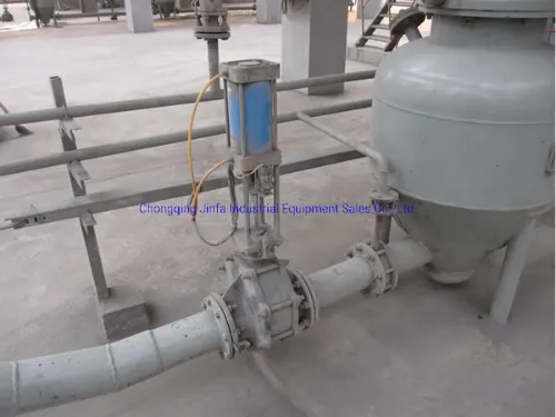
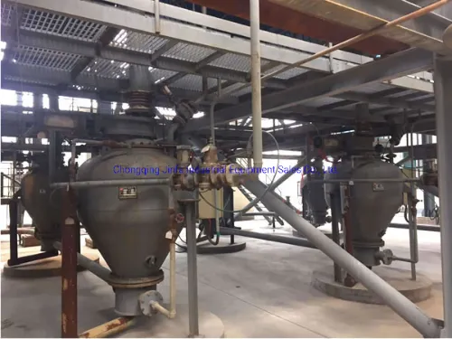
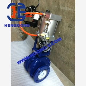
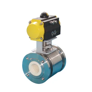
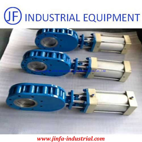
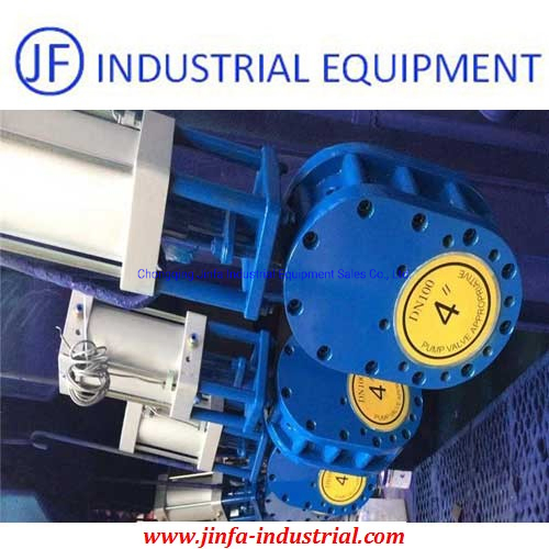
This valve is mainly used in the fly ash pneumatic conveying system of thermal power generation enterprises, as a warehouse pump discharge valve, balance valve, exhaust valve, and plugging valve. It can also be used as a pipeline switching valve and an ash unloading valve. At the same time, it can also be used for opening and closing the pipelines with various wearable dry dust, water, steam and other media such as cement, mining, papermaking, and chemical industries.
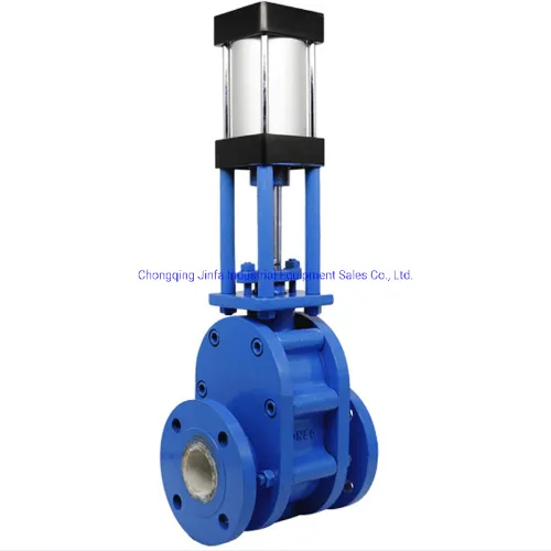
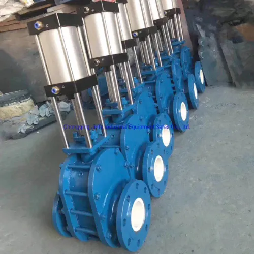
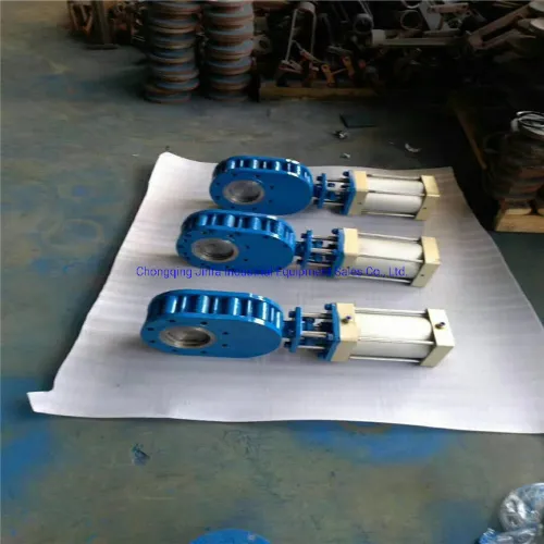
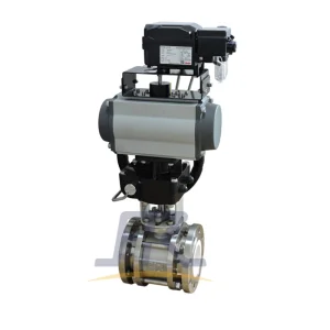
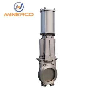
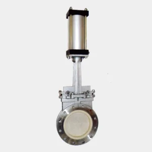
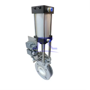
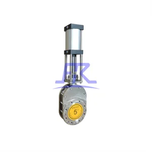
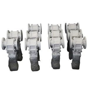
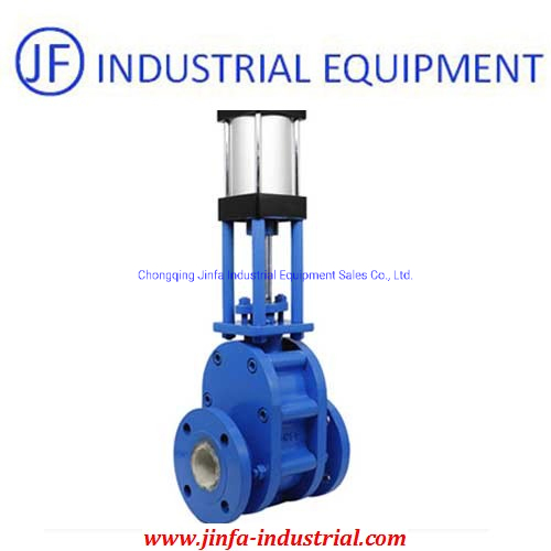
This double gate valve provides bi-directional sealing. The valve body features precision cast steel, while sealing components utilize wear-resistant and high-temperature resistant fluorine rubber. The sealing surface between the valve plate and seat is crafted from toughened structural ceramics or cemented carbide, reaching a hardness of 60~70HRC. This ensures a service life 5-10 times longer than ordinary valves, offering superior wear resistance, high temperature resistance, and low starting load.
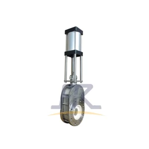
Operating via air input, the valve stem drives the plate downward to close and upward to open. A spring-loaded mechanism ensures the plate remains pressed against the seat, compensating for thermal expansion and preventing particulate entry. During operation, the valve plate rotates to provide a grinding/polishing effect. The eccentric body design creates a material vortex during discharge, facilitating a self-cleaning lumen effect.
| Model | DN | L | D | D1 | D2 | b-f | n-Φd | H |
|---|---|---|---|---|---|---|---|---|
| Z674Tc-10C | 50 | 200 | 160 | 125 | 100 | 20-3 | 4-18 | 520 |
| 65 | 220 | 180 | 145 | 120 | 20-3 | 4-18 | 595 | |
| 80 | 240 | 195 | 160 | 135 | 22-3 | 4-18 | 635 | |
| 100 | 280 | 215 | 180 | 155 | 22-3 | 8-18 | 630 | |
| 125 | 300 | 245 | 210 | 185 | 24-3 | 8-18 | 715 | |
| 150 | 320 | 280 | 240 | 210 | 24-3 | 8-23 | 840 | |
| 175 | 320 | 310 | 270 | 240 | 26-3 | 8-23 | 885 | |
| 200 | 350 | 335 | 295 | 265 | 26-3 | 8-23 | 1155 | |
| 250 | 400 | 390 | 350 | 320 | 28-3 | 12-23 | 1400 | |
| 300 | 450 | 440 | 400 | 368 | 28-4 | 12-23 | 1800 |
1. Verify valve model and technical parameters against the manual before installation.
2. Prohibit flange welding after installation. Ensure appropriate distance and use gaskets on both flange sides.
3. Maintain coaxial alignment between pipelines and valve diameter. Flange surfaces must be flat to ensure uniform bolt tightening and normal operation.